Location:
Photovoltaic (PV) Power Generation


Application
Three-phase string inverters perform energy conversion in conjunction with series-connected photovoltaic panels. Their rated power ranges from a few kilowatts to 300 kW. String inverters typically adopt a two-stage power conversion circuit, and most inverters are designed without a transformer or with a non-isolated transformer. The DC/DC conversion unit converts the variable DC voltage into a fixed DC voltage while extracting maximum power from the PV panels through maximum power point tracking (MPPT) technology. The DC/AC conversion unit then converts the DC power into grid-compatible AC power. Both two-level topology and three-level topology can be used for power conversion in this unit, with three-level topology being preferred for its higher efficiency. For 1000 V PV array systems, the three-level NPC1 or NPC2 topology is mainly used. The three-level NPC1 can use 600 V power devices, and even in systems with oversized PV panels, the power devices can operate at switching frequencies above 20 kHz. The three-level NPC2 requires both 600 V and 1200 V power devices; this topology is well suited for device operation at switching frequencies below 20 kHz. In 1500 V PV systems, the three-level ANPC topology is widely used due to its higher reliability considering cosmic ray factors and its high efficiency over the full power factor operating range.
Central inverters have rated power ranging from 600 kW to 3000 kW. Central inverters typically adopt a single-stage power conversion, and are usually designed with a transformer or with an isolated transformer. In the DC to AC stage, the variable DC power is converted into grid-compatible AC power. In this conversion unit, two-level or three-level NPC1, NPC2, and ANPC topologies can be selected. Three-level topologies are widely used for their higher efficiency. For 1000 V PV systems, the three-level NPC2 topology is often preferred. 1500 V PV systems are becoming increasingly popular. The three-level NPC1/ANPC topologies enable a more robust inverter design.
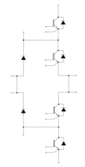
Principle topology diagram


Photovoltaic Power Generation Schematic Diagram

Photovoltaic Power Generation Topology Diagram
Topology Structure Table
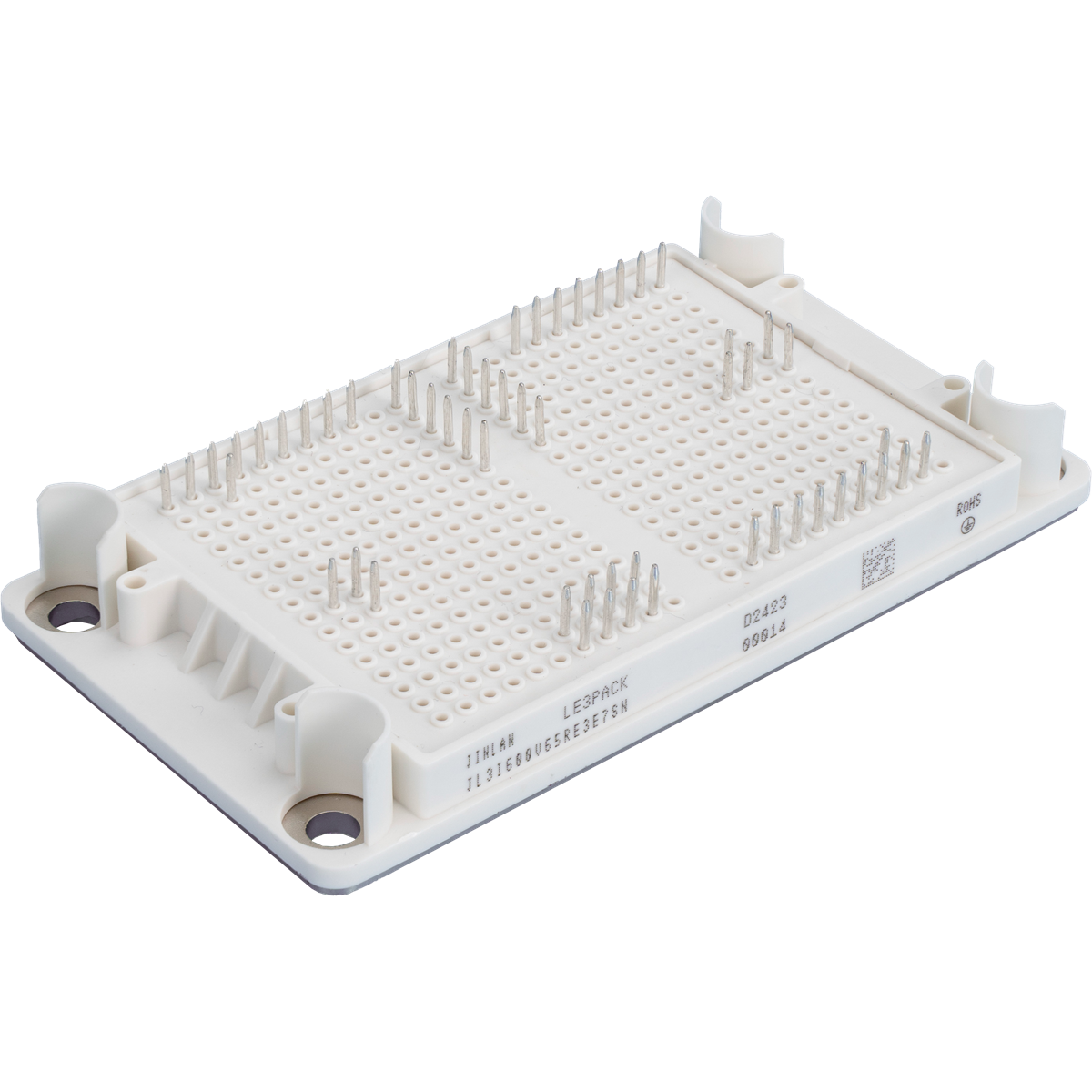
| Topology | Package | Model / Part Number | Outline / Dimensions |
| E3 | JL3I600V65RE3F7SN |
|
| E3 | JL3I600V100RE3E7SN | ||
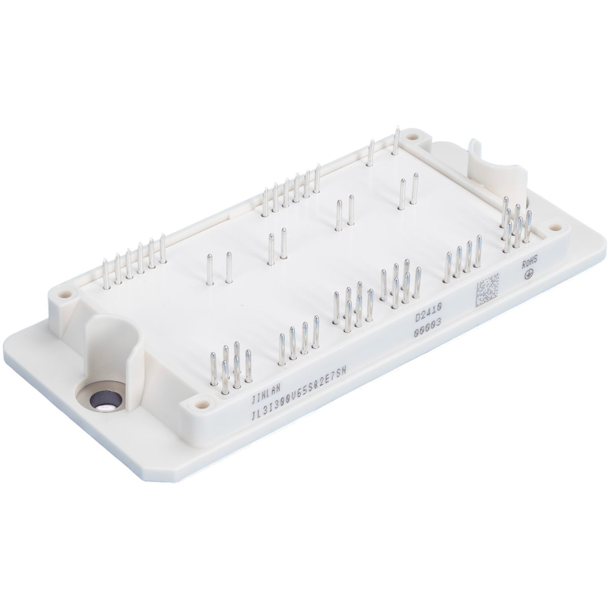
| Q2 | JL3I300V65SQ2E7SN |
| |
| Q2 | JL3I450V65RQ2E7SN | ||
| Q2 | JL3I600V65RQ2E7SN | ||
| Q2 | JL3I400V100RQ2E7SN |